|
Overhead catenary on the Bernina Bahn
On this page I've first put the overhead catenary of Alp Grüm with a description
because this is the most interesting part due to the hairpin turn.
Next you will find the description of the station of Campocologno.
|
|
Our layout has to be equipped with Overhead wire, just like the original.
In model this is a job in itself because of the separations between the modules
that are needed for transport. The overhead wire must be tiled here and be able
to be taken apart without compromising the quality. This forms a challenge while
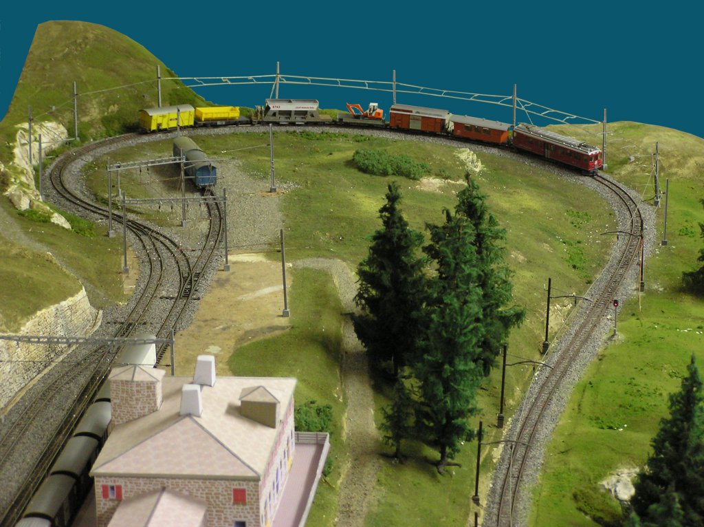
keeping the wire under tension. The turn underneath the station of Alp Grüm has
a special way of overhead construction. In the hairpin turn, the wire has not
been constructed in the usual way, it has been suspended only by the hanging wire.
The driving wire does not touch the post anywhere.
Click on the photos and drawings to get an
enlargement in a new window.
|

|
|
Wire scheme of Alp Grüm station
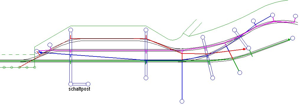
In the scheme above you can see how the individual wires traverse the
station of
Alp Grüm. One post catches the eye, it is positioned very far away
from the rails. This is done to prevent pedestrians from running
into it because it is right at the pedestrian crossing of the path
to the upper restaurant.
Here too you can click on the drawing to get a better picture. The
green wire comes from the direction of the pass. It ends in the
station where it is put under tension. The pink wire begins in the
station and continues down the hairpin curve. It is terminated
shortly after the turn. The red and blue wires remain entirely
within the station area.
In our model we will use this same scheme.
|
|
|
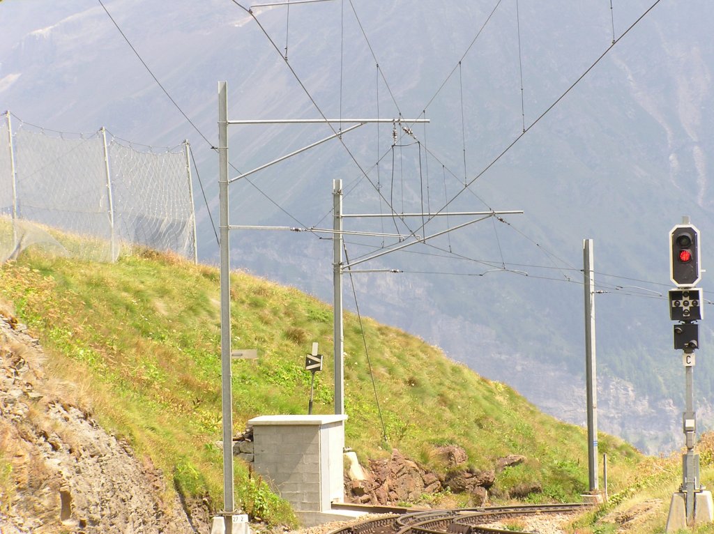
Changeover to the sharp turn
This photo of the original shows the transition from normally
suspended overhead wire to the stretched wire used during the turn.
On the first post, both the upper and the lower wire are directly
attached. On the middle post, the upper wire is directly attached
but the lower wire is pulled to the side by a special attachment,
consisting of a thinner part from the post and a thicker, curved,
part connecting to the lower wire. The rear post only holds the
upper wire and the lower wire hangs free during the whole turn,
connected to the pole via supporting wires. All supporting wires
that hold the lower wire are made of two parts, a thin part from
the upper wire and a think, curved, part to the lower wire.
This is done to prevent the pantograph from touching the supporting wires.
|
|
|
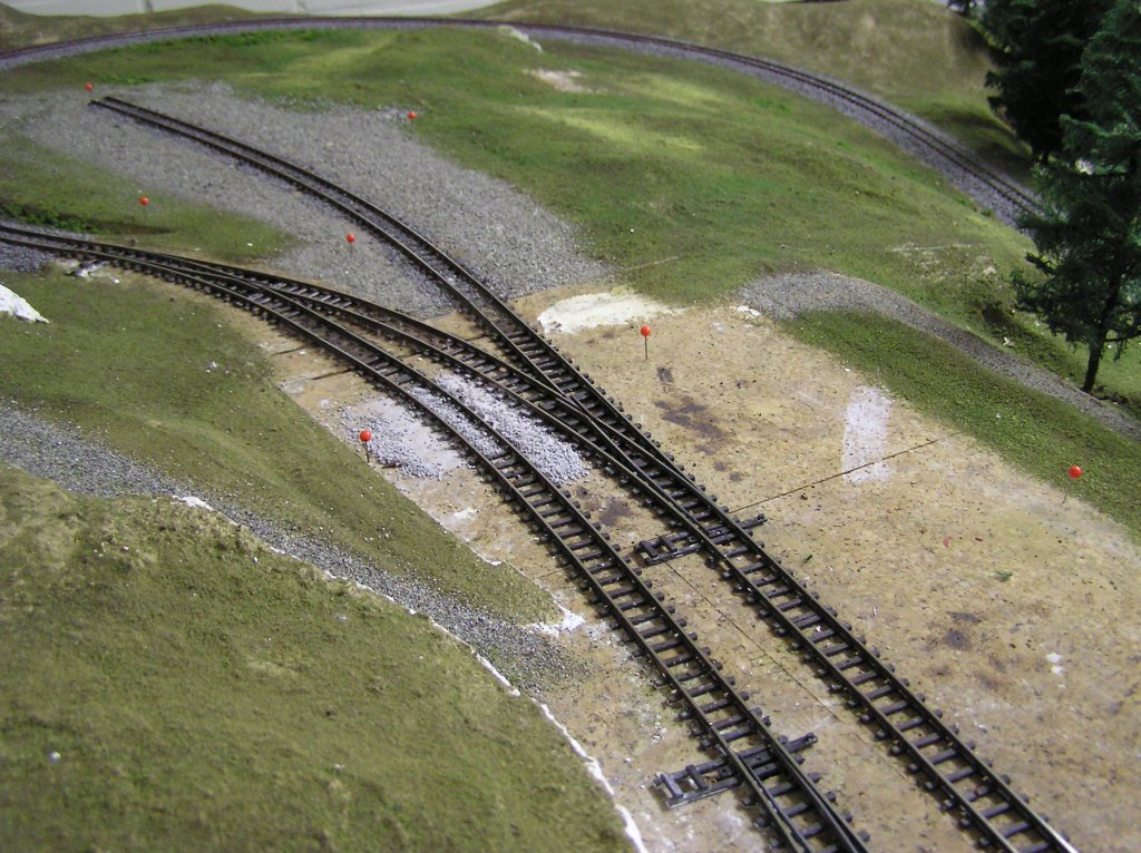
Marking the positions of our poles
Dec 2003
In the model station of Alp Grüm we started to mark the locations of the
poles that should carry our overhead wires. We did this through
orange pins.
On a number of places the poles will be connected to form a portal but this
is not used everywhere. because of the narrow turns we need to put
some extra poles in between to hold the wire in the middle of the
rail.
|
|
|
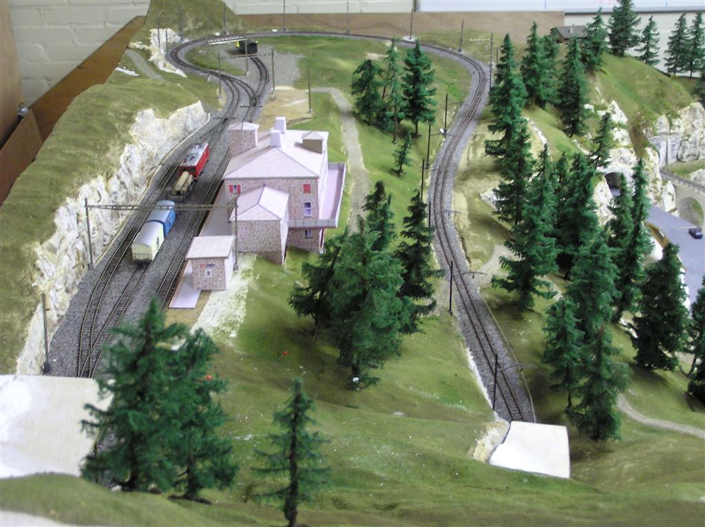
The first portal is standing
Alp Grüm in a later stage
(Christmas 2004), A part of the overhead catenary has taken its
place. In particular the turn after Alp Grüm. It showed that we have
to, just as in reality, tie up the poles in the curve to keep them
straight.
|
|
|
The wire has been installed
Situation 2006, Station Alp Grüm completely wired. Also the special
overhead wire in the turn is well visible. The material we used for
the horizontal wires is bronze, 0,7 mm thick. The wires have the
complete length of the station so that we don't need any weldings.
The little vertical wires are made of messing wire, 0,5 mm thick.
That is a lot easier to solder and cut. In order to bridge the gap
between two modules, we used short, ready made pieces by Sommerfeldt.
They can be removed easily for transport.
|
|
A short manual
For fastening the vertical wires we took the following approach;
You start by cutting off several wires to the desired length plus
about 1 cm. Those pieces can be attached to the lower wire by a
clothes peg. Do it so that the clothes peg only holds the vertical
wire and can still slide it over the lower horizontal wire. In this way
you can move all needed wires to a nice, equal distance. Now it is
easy to solder them one by one to the upper wire. the clothes pegs
can be removed and you can solder the other side to the lower wire.
Cut off excessive metal and make them smooth on the bottom. We did
that with an abrasive round stone on a mini drill. Ready to drive.
|
|
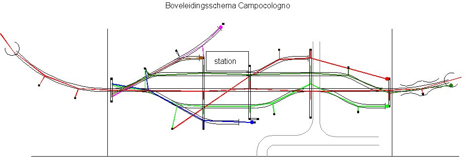
Wire scheme of Campocologno station
|

|
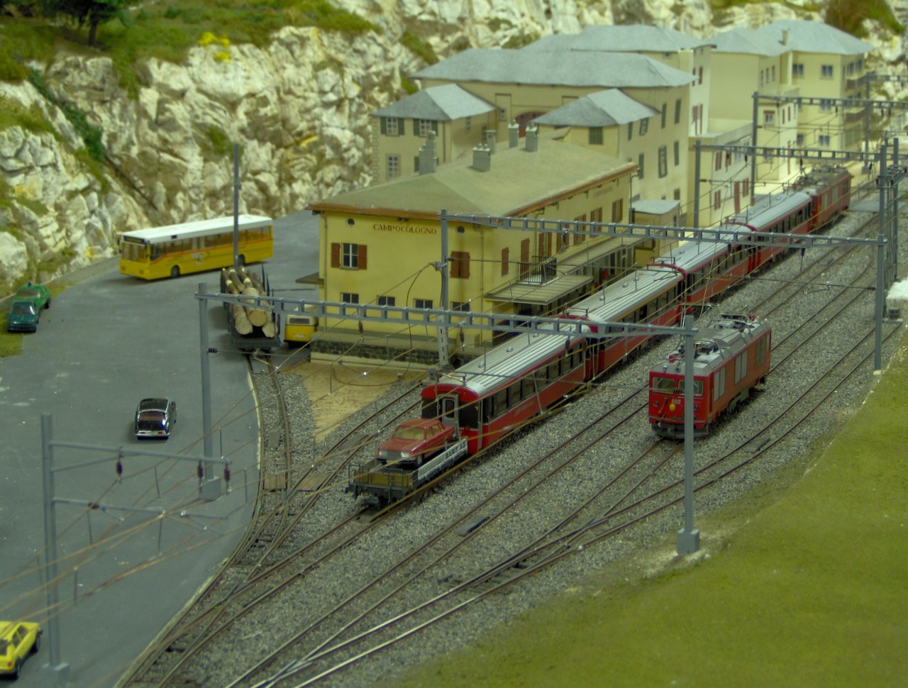
Campocologno under construction by Johan and Steef.
|
|
June 2006. The lower wires are ready, the upper wire and the
connecting wires are still to come.
|
|
April 2007. The overhead catenary is almost done.
A few pieces on the shunting tracks still have to be done but due to
lack of the right wire it can take a while.
Sunday 1 April 2007 we used the overhead catenary for the first time.
Click here for a small film in QuickTime format.
|

|
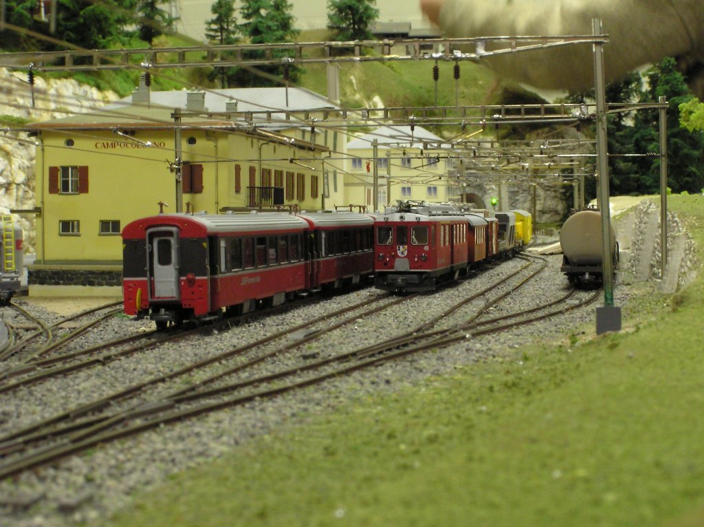
March 2008. De overhead wire can be shown at Rail.
All station tracks are under wire now.
The overhead wire is also powered, which is used for the internal
lighting of the train. The headlights and the lights in all
carriages burn constantly as long as the pantograph touches the
overhead wire. Also when the train comes to a halt as show on this
picture.
|
|
Tunnels ?
We did not make overhead wire everywhere in the tunnel. We omitted that
on all places where we had enough space to have the pantograph upright,
that would only have complicated things. An exception is the spiral.
Here the height till the track above is not enough and so we did attach
a thick wire to the ceiling using metal strips. We used electric
installation wire (1,5mm). Also directly behind all tunnel entrances we
used this wire to "catch" the pantograph. Mounting the wire
under the spiral was best done by putting the complete module upside down.
Then you can easily solder everything into place. To determine the position
of the wire we used a specially prepared wagon with a pencil mounted on top
of it. A spring held it to the ceiling while driving over the rails.
This gave a nice line on the ceiling which could be used for positioning when soldering.
Hans Hosang
|