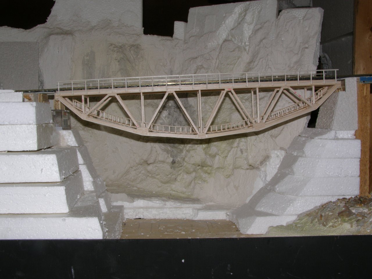
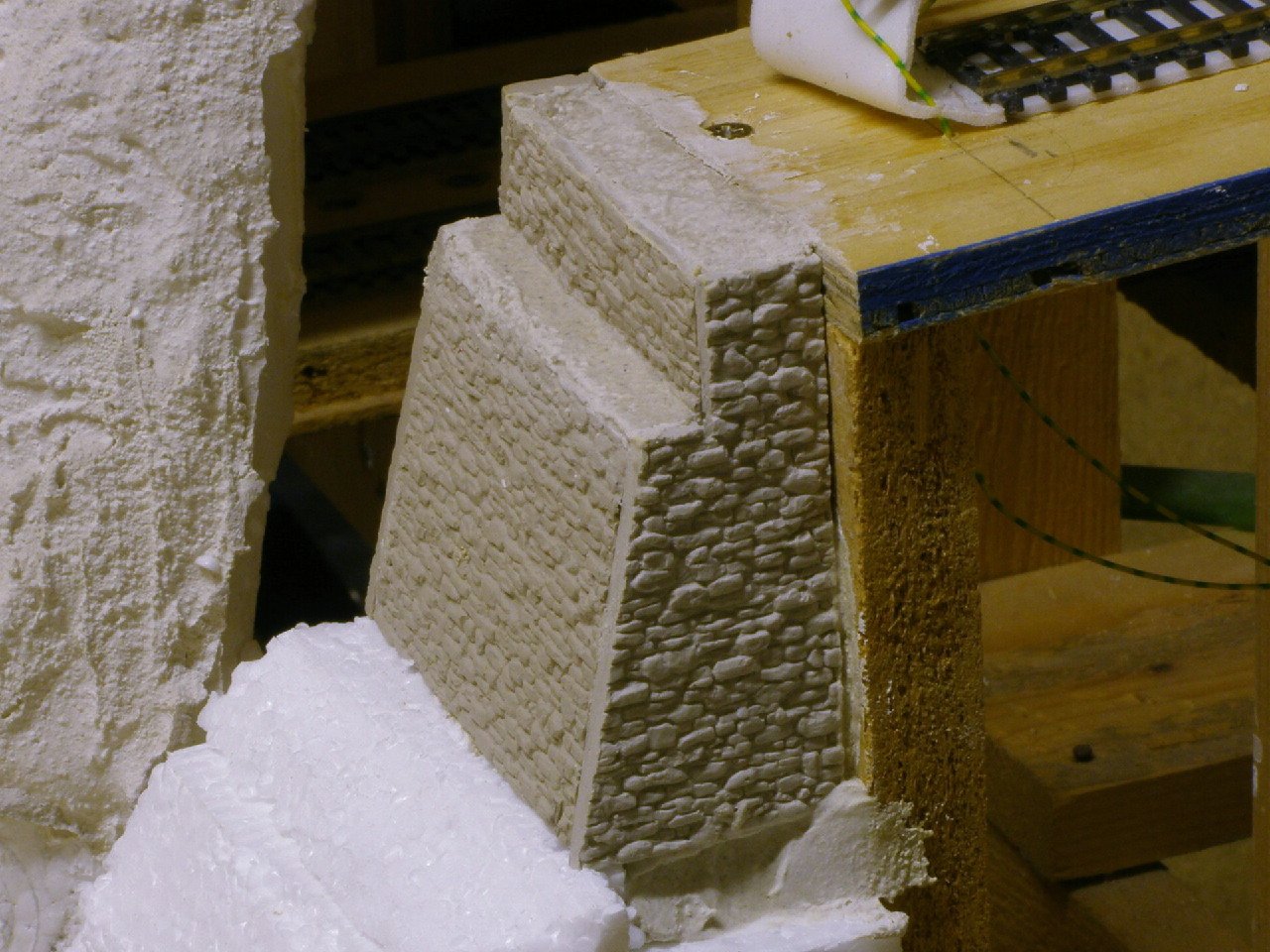
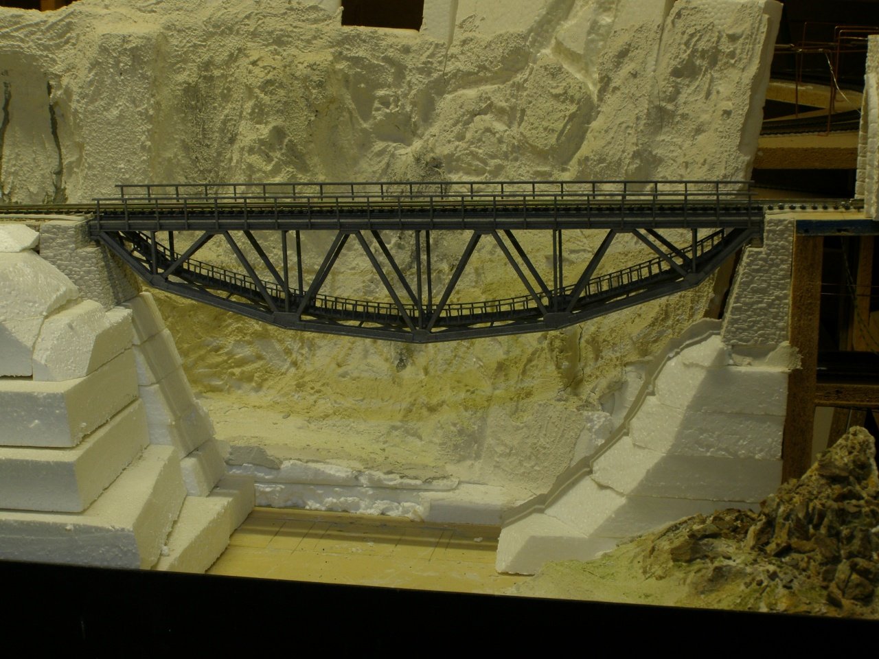
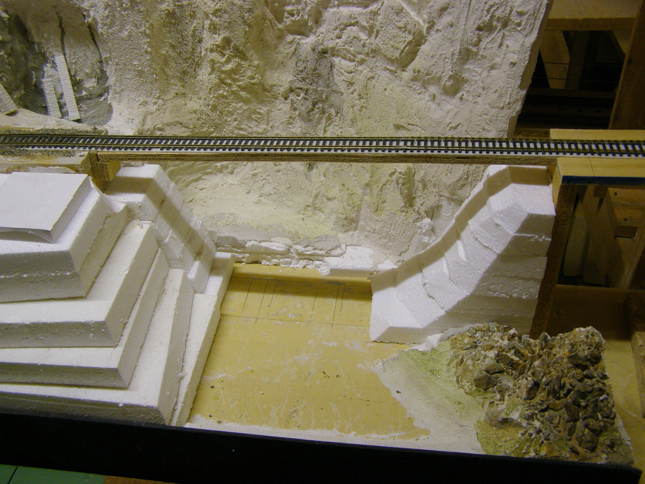
How to make a girder bridge from Balsawood

The beginning

One starts with empty space, a hole that needs to be bridged because the track can't get around it.
Please note here that for me the model layout is leading, I don't (de)form the layout to fit in a sale model of an object.
Normally I'll put may rails on a surface of fiberboard or multiplex. I continue this over the space that needs to be bridged, that enables me to start driving. There where the bridge will come I reduce the width of the wood to the size of the rails (3cm for H0), so it is clearly marked where the span will come. That works better for me to give an image. After that I'll create the sides with a few blocks of Styrofoam. So, now the sizes are known.

My gap.

The bank on each side of the narrow part, made of blocks of Styrofoam, have been glued together with quick drying plaster. Then you are done in a few minutes. You can also do it with white wood glue but that sets very slowly. The Styrofoam doesn't have a flat surface so you can't squeeze the glue out to a slim layer.
Click on the photo for an enlargement in a new window.

Finding your bridge

Now the sizes are known, I'll start the search for a bridge that matches my ideas.
In this example I ended up at the Sarengraben bridge near Kandersteg in the Lötschbergbahn. I used the book "Lötschbergbahn im Bau" that has been published for the 75 anniversary of the line by "Verlag Eisenbahn" in 1989. This is a bridge that is 60 meter in length and that is in Model a bit too large for my gap of 44 cm. So it needs to adjusted a little bit. For me the result is more important then being exact on scale, it should fit the surroundings. I shortened the bridge by 2 sections.

The original

Here a photo of the Sarengraben bridge, taken during the final bridge test in May 1913. This photo has been copied from the book "Lötschbergbahn im Bau", Verlag Eisenbahn 1989.

The drawing below has been created on the computer to fit my layout. This took me about 8 hours.
You can get en enlargement of the drawing by clicking it.

Gluing on the drawing.

I use the drawing as surface for building the bridge sides. Printed on the right scale, I glue the sheets together and put it on the table. From a sheet of balsawood, size 10 by 100 cm, 1 mm thick, I cut strips of 4 mm wide to create the upper and lower edges of the bridge. In between the lower strips you glue scares where the vertical beams will be mounted. I glue all the pieces together with the drawing as underground. See photo next to here. As glue I use quick setting white wood glue.
Click on the photo for an enlargement in a new window.

A girderbridge dating back to the beginning of the last century was constructed from a combination of steel plates and L-profiles, This in contradiction to the now common H-profiles. Also they riveted everything together in stead of the current welding method. The vertical and slant beams used to be constructed from 4 L-profiles with met cross connections. This was put together to 2 U-profiles with small connections. This was impossible to model out of Balsawood in H0. I've tried to mimic this from 2 strips of 3 by 1 mm connected with small connections of 2 mm wide and 6 mm long. That looks just the same from a small distance. A pair of tweezers will come in handy while doing this, else it is very difficult to fit it correctly. The beams have a size of 3 by 4 mm.

First side ready.

On the photo you see one side of the bridge completed.
On the sides you see small scares of balsawood, the original has plates fitted there to keep the parts of the arch together. These scares still have to be reduced with a piece of sanding paper.
Click on the photo for an enlargement in a new window.

Second side under construction.

Also for the second side I use a print of the drawing and glue the parts together as described above. The first drawing didn't completely survive the release of the firs bridge half. I cut it loose with a small Stanley knife. Some little pieces of paper do stick to the bridge but can be removed easily by a sanding paper.
Click on the photo for an enlargement in a new window.

2 sides done.

While enjoying a good glass of wine I hang the 2 parts of the bridge between 2 temporary walls to get an impression of what it will look like. The top of the 2 sides have been given a finish with a 1,5 mm thick strip of balsawood of 7 mm wide.
Click on the photo for an enlargement in a new window.

The connecting parts.

On the upper side of the bridge solid beams connect the sides that need to support the train but on the lower side the designers tried to spare weight and used fragile girder connections. For the beams on the upper side I used 2 by 3 mm strips, with 5 mm in between. The girder I made from little pieces of 1 by 1 mm. A pair of tweezers will come in handy while doing this, else it is very difficult to fit it correctly.
Click on the photo for an enlargement in a new window.

Connecting the 2 halves.

Now I put the bridge upside down and make sure it stands rectangular. The upper beams are glued to the first side, there where the vertical and the slant supports join the bridge deck. Under each beam I've put a filler of 1,5 mm thick (as thick as the finishing of the sides) in order to keep things rectangular.
Click on the photo for an enlargement in a new window.

Intermediate result.

After the upper beams have been mounted on one half of the bridge I glue the second half to it. Make sure that you keep enough room on the bottom to fit the girders in between later on. It's not too bad if the space a is a little tight but it may never be too wide. Next the girders will be placed in between the under side of the bridge halves. The photo shows the result.
Click on the photo for an enlargement in a new window.

Rail carriers.

Now it's time to fit the beams that will carry the rails on top of the bridge. In the book "Lötschbergbahn im Bau" you can find a very accurate description of how this is done with the original bridge. Deducted from these pictures, I created connective parts between the rail carriers and glued the carriers to them. For lining them I used a long ruler. The carriers have been made of strips sized 3 by 1 mm, 2 horizontal and a third vertically in between.
Click on the photo for an enlargement in a new window.

The footbridge.

All Swiss girder bridges I've seen so far have a small footbridge for inspection. Also the Sarengraben bridge has one. I've use 2 strips of 1 by 1 mm and put them on the girders on the bottom of the bridge, about 10 mm apart. Over them I've glued planks of 2,5 to 3 mm by 10 mm with about 0,5 mm in between.
Click on the photo for an enlargement in a new window.

Railings.

De footbridge needs railings. I cut small strips of 1 by 1 mm, 10 mm in length. If you cut a strip of 10 mm wide, crosswise to the vein of the wood, it is pretty easy to cut off 1 mm pieces. These I've glued to the side of the footbridge, about 2 planks apart.
Click on the photo for an enlargement in a new window.

Railing footbridge ready.

For the railing of the footbridge I used a strip of balsawood, a little less then a millimeter and glued it to about 10 poles at a time to the bridge. Just hold it a few minutes and on the the next 10 ... One and a half hour later both railings are done.
Click on the photo for an enlargement in a new window.

Cross connections on the lower side.

To give the bridge sideways stiffness it should have some cross connections on the bottom. Many bridges have this kind of cross connections also vertically but because this bridge is situated on a straight track this was not needed here. This makes the bridge a lot easier to build. Along the underside I've put two strips of 1,5 mm thick balsawood to make the sides into T-profiles. Between the T-profiles there is an opening to let rainwater through.
Click on the photo for an enlargement in a new window.

Upper railing.

By now I also started to make the railing on the upper side of the bridge. I glued every 2 cm a small piece of balsawood in order to hold the railing. Underneath I glued a small strip to make the horizontal beam look like an H-profile.
Click on the photo for an enlargement in a new window.

Fitting it.

Most work is done, the bridge is roughly  ready.
with a saw I removed the wood that held the rails temporarily. Now its time for a final check if it fits as expected. I've put the bridge on a couple of wood blocks since the bridgeheads are not ready yet. On the right hand side a first bridgehead is placed of loose plaster molds.
Click on the photo for an enlargement in a new window.

Bridgehead on the right hand side.

Using molds by "Anita Decor" I made plaster walls and cut them into the bridgehead that you can see on the photo next to here. The inside had been filled with "roodband" plaster by Knauf. This gives you a nice long time to use it before it sets. I also used that plaster to glue the parts of the bridgehead together. Do make sure that the wall parts are completely wet before you apply new plaster. As an alternative you can use white wood glue to fix dry plaster parts together. But, fastening plaster with plaster gives a stronger bond compared to white wood glue.
Click on the photo for an enlargement in a new window.

Bridgehead left.

The left side bridgehead under construction. The stone structure on the edges has been continued using a dentist drill.
Click on the photo for an enlargement in a new window.

Painted.

The bridge has been painted using an airbrush with the color "gun-metal" by Humbrol (number 53). I thinned this 1 to 1 with benzine.
Click on the photo for an enlargement in a new window.

Bridgehead left.

Also the bridge supports have been placed, just need to give them the right color. Only the access to the footbridge is still missing, that needs to pass between the bridgehead and the support. I'll finish the landscape a bit further before I start that.
Click on the photo for an enlargement in a new window.

Bridge test.

Test, test, test and Yes, It works great.
Now still to fit the overhead catenary.
Click on the photo for an enlargement in a new window.

This is a "living" document.
Above you see the current situation of the bridge (dec-2007).
This will remain so for a while.
The bridgeheads I'll paint when I'll do the rest of the rock face around the bridge, which is far from complete now.

Hans Hosang.